Solving LED Flicker in Long-Run Commercial Pool Lighting: A Technical Engineering Guide
For commercial project managers and MEP engineers, intermittent flickering in underwater lighting is frequently misidentified as a faulty fixture. In our factory experience, approximately 70% of reported flickering issues stem from electrical infrastructure deficiencies, such as undersized wiring or improper power supply selection, rather than intrinsic LED failure. This guide provides an engineering-led approach to diagnosing and correcting these signal instabilities in large-scale installations.
The Physics of Flicker: Differentiating Voltage Drop from PWM Noise
Flicker is generally a manifestation of either unstable voltage delivery or incompatible Pulse-Width Modulation (PWM) dimming signals. Voltage drop causes a visible dimming or shift in intensity when the load exceeds the wiring capacity, whereas PWM noise appears as a rapid strobing or stuttering effect. Proper Led Pool Light systems require clean power delivery. If the driver cannot process the incoming waveform due to signal degradation over long runs, the LED will struggle to maintain a consistent output.
Decoding Ohm’s Law in 100m+ Pool Lighting Runs
As distance increases, the resistance of the copper conductor significantly impacts the voltage delivered to the fixture. In long-run installations, failure to account for this resistance leads to DC voltage decay. Our Calculating Voltage Drop Wire Pool data confirms that even slight deviations in load can lead to system-wide failures. The following table illustrates the necessity of selecting the correct gauge for your specific run length.
| Load (Watts) | Distance (50m) | Distance (100m) |
|---|---|---|
| 100W (12V) | 10 AWG | 8 AWG |
| 100W (24V) | 14 AWG | 12 AWG |
Engineering Solutions: High-Frequency Drivers and Signal Integrity
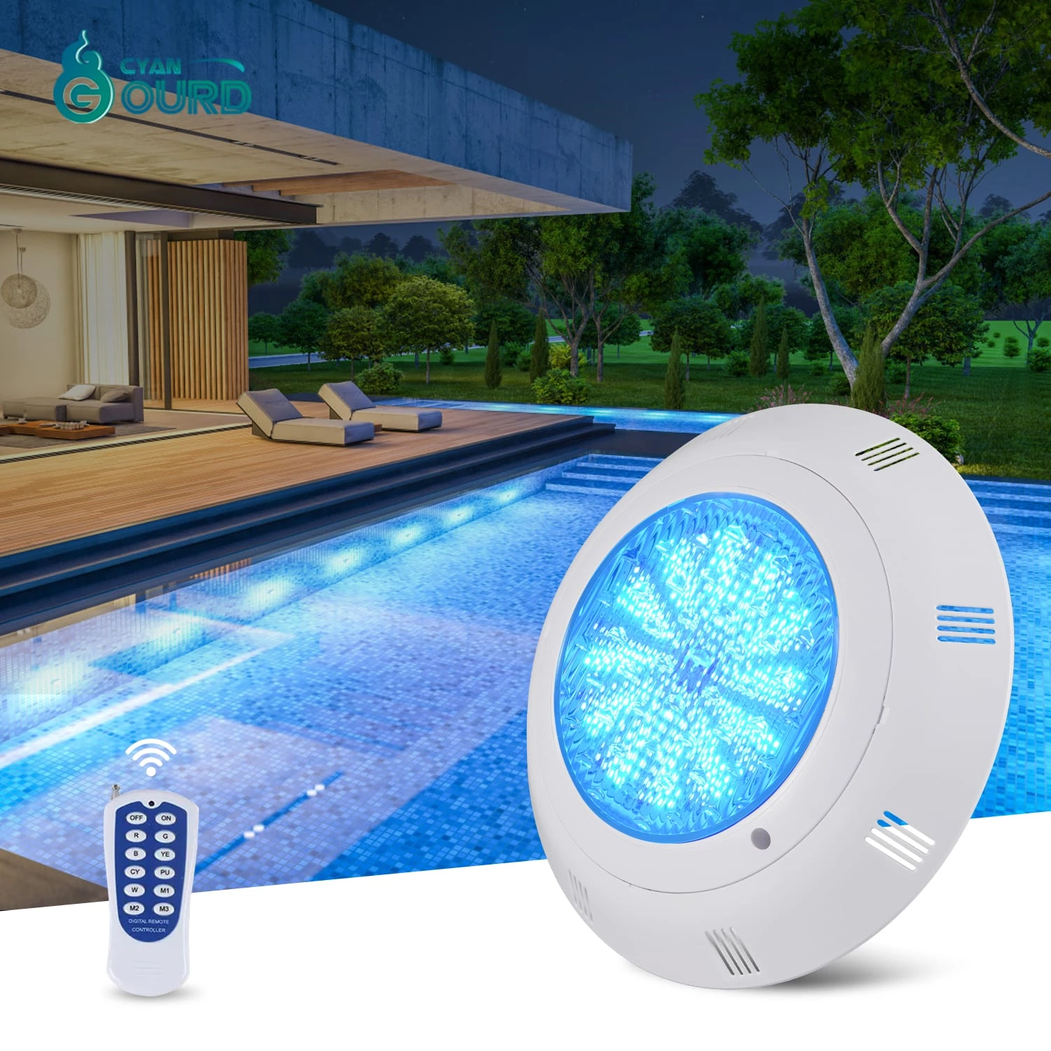
Our internal testing using YC-series drivers demonstrates that high-frequency PWM stability is the antidote to flicker. Oscilloscope captures show perfectly stable waveforms over 100m runs when using high-impedance matched drivers. In our production line, we prioritize components with a high Mean Time Between Failures (MTBF) to ensure that the integrated drivers remain consistent under the thermal stress of underwater operation. Our Stainless Steel Pool Light models, such as the YC105/165/205-SP, are engineered with these specific high-frequency design requirements to prevent signal degradation.
Procurement Checklist: Identifying 'Under-powered' vs. 'Incompatible' Drivers
When sourcing for large projects, prioritize data over price. An under-powered driver lacks the overhead to compensate for minor voltage dips. Conversely, an incompatible driver may not support the necessary PWM frequency range for your dimming system. Always verify that drivers meet the specific amperage requirements of your chosen Nicheless Pool Light units, such as the QR-55, which operates efficiently at 3W/6W/9W power configurations.
Installation Best Practices: Preventing DC Voltage Decay
Preventing decay requires strict adherence to IP68-rated modular cabling systems. During factory audits, we have found that improper joint sealing is a common source of impedance fluctuations. Using high-quality, factory-validated cabling prevents environmental moisture from entering the signal path and causing intermittent resistance changes. For the Embedded Pool Light series, specifically the QR290-A, we emphasize precise sealing protocols to maintain electrical integrity over the product's lifespan.
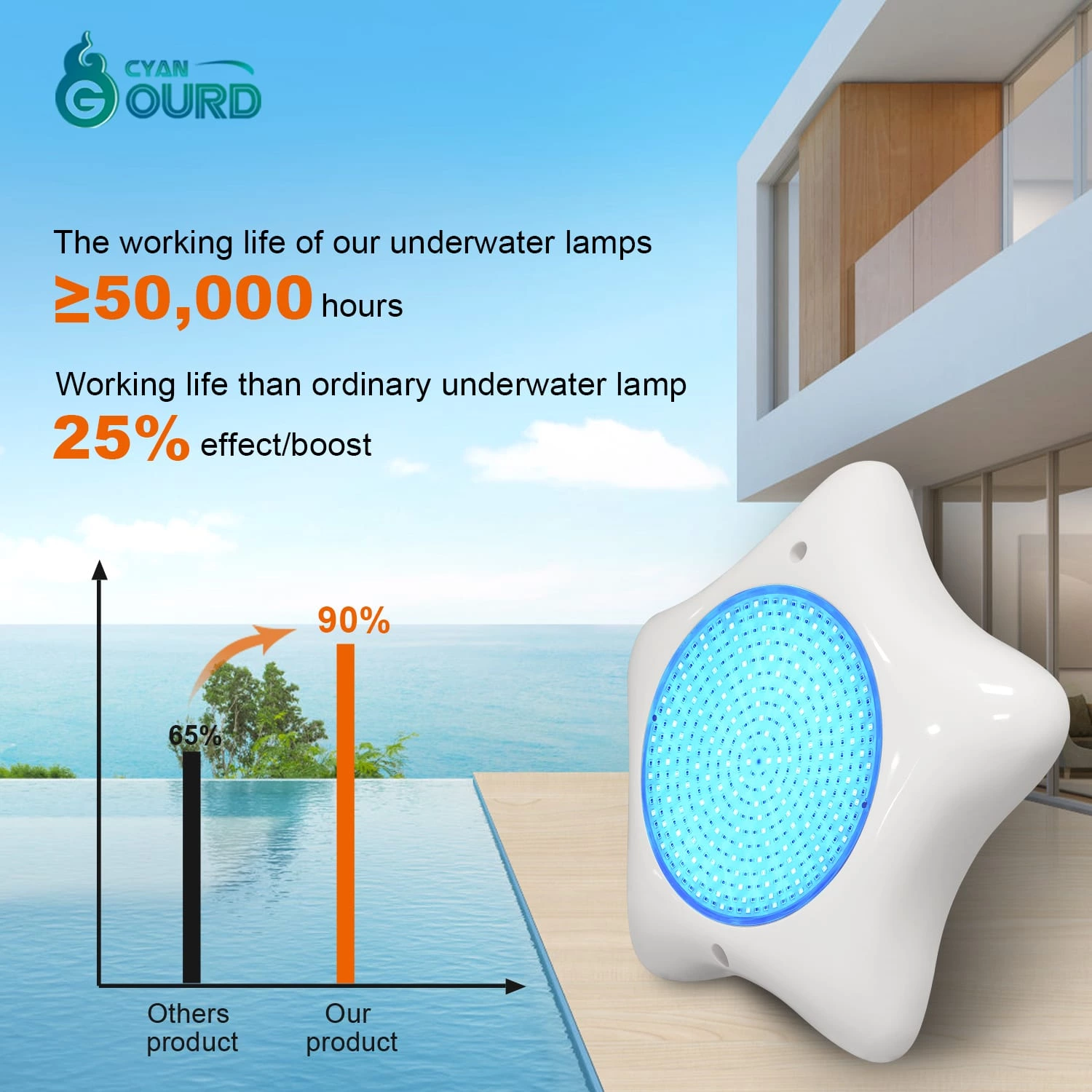
Quality Control Protocols: How We Stress-Test for Harsh Environments
Reliability starts with rigorous testing. We validate our connectors against the IEC 60529 (IP68) standard, ensuring they remain protected under long-term submersion. Our production process includes multiple stress-test checkpoints, including thermal cycling and power-load consistency tests, which are essential for products like our ABS+PC units. By maintaining stringent QC, we ensure that our drivers consistently meet the required MTBF targets for commercial aquatic facility environments.
Troubleshooting Roadmap for Project Managers
Q: What is the primary cause of flicker in 100m pool lighting runs?
A: The most common cause is voltage drop due to insufficient wire gauge (AWG), which starves the LED driver of the necessary DC voltage to maintain a steady signal.
Q: How do I test if my driver is compatible with a third-party dimmer?
A: Check the PWM signal range of the driver against the dimmer output. Drivers must be matched to the frequency requirements specified in the technical data sheet to avoid strobing.
Q: What does IP68 rating imply for underwater reliability?
A: It confirms the enclosure has been tested to withstand long-term submersion without moisture ingress, which is vital for preventing electrical shorts that lead to flickering.
Q: Can I use standard market-grade drivers for all commercial pool lights?
A: No. Commercial pool lighting requires drivers with higher MTBF ratings and specialized circuitry to manage voltage fluctuations inherent in large-scale aquatic installations.
Q: How does cable impedance affect color consistency?
A: High impedance causes uneven voltage distribution across the string, leading to visible color shifts or dimmed intensity at the end of the line compared to the start.
Conclusion: Partnering for Reliable Commercial Aquatic Installations
Successful large-scale aquatic projects depend on proactive electrical planning. By understanding the interaction between cable gauge, PWM signaling, and driver MTBF, project managers can eliminate the primary sources of lighting flicker. We invite you to contact our engineering team to download our full Technical Troubleshooting Spec Sheet to ensure your next installation maintains peak operational integrity.